
S3. Intro to Physical Computing
Description
Creating a conversation between the physical world and the virtual world of the computer, with a process of transduction.
Start Date: Wednesday, January 30 2013
Due Date: Midnight of Tuesday, February 5 2013
Readings
- Physical Computing (Introduction and chapters 1, 2 & 3) by O’Sullivan and Igoe
Lecture Slides
Available here.
Instructions for the Lab Assignment
This lab will serve to get the Arduino environment set up on your laptop and to familiarize yourself with building circuits around the arduino hardware. We will be using pre-existing code and the arduino board to control an LED and make it blink.
Steps
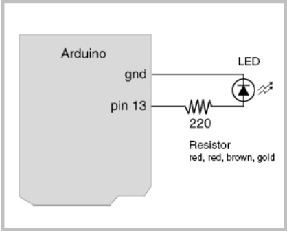
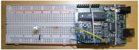
- Go through the initial tutorials on setting up the Arduino environment on your laptop and to complete the blinking LED lab. Instructions for different platforms are available directly at http://www.arduino.cc. Here are direct links to the more common platforms: Windows, Mac OS X. and Linux.*NOTE: In step 9, they refer to the onboard LED. Please ignore this and build the circuit shown in the images below.
- Try to have the LED blink in different speed. (This process ensures that LED is not blinking due to the existing program on Arduino but you are indeed uploading your own program to your Arduino successfully.)
- Submit your report to the student pages: Click here to create a new assignment page. (Note: It'll probably look very much like the one we showed in class. That's okay. As long as it has your own photo in it.).
- For this assignment and all other assignments, we will be asking you to post both image(s) and description of your project. Please look at the following sample page for what your web posting for the first assignment should look like: http://courses.ischool.berkeley.edu/i262/s13/content/elliot/sample-lab-submission
Hints
- Use one color wire when attaching things to source (positive terminal)
- Use a differnt color wire when attaching things to ground (negative terminal)
- Be consistent and always use the same color for source and for ground. This helps prevent errors.
- Keep things neat
- LEDs are polarized. The short leg must go to ground
- The 220-ohm resisitor is labeled red, red, brown, gold. It is not polarized
Click here to post your assignment.
Drupal theme by Kiwi Themes.