Assignment: Sensing: Potentiometers
Collaborators:
 Description:
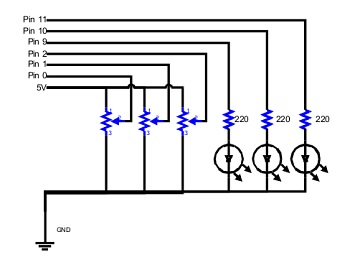
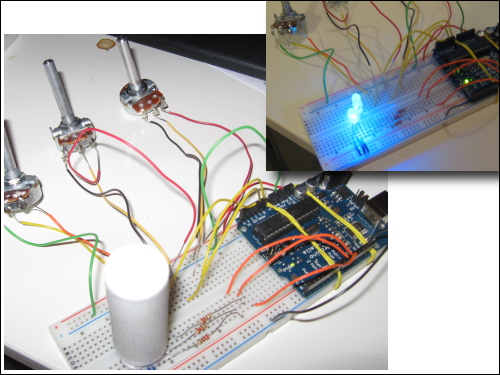
This project is a demonstration of the use of Potentiometers (variable resistors) to control various aspects of LED display, such as blink rate, fade, and color display. This project builds upon the basic circuitry of Project #2, but adds an aspect of control which utilizes the Arduino Board's analog input pins. In order to attach the potentiometers to the breadboard, we soldered jumper wires to the potentiometer outputs.
Components List:
Notes:
I decided to create a 3-Potentiometer circuit, in which one potentiometer controlled the blink rate of all three LEDs, another controlled the fade of all three, and the last one toggled through every possible color combination that could be displayed. I used the sample 2-potentiometer Fade/Blink code as a base for my final code.
Code used in this Assignment:
/*
* 3 Potentiometer AnalogInput
*
* Pot 1: Controls Fade of all 3 lights
* Pot 2: Controls Blonk Rate of all 3 lights
* Pot 3: Cycles through which lights are on!
*
* by Michael Manoochehri
* Based on one pot dims, the other pot changes the blinking rate found here:
* http://www.arduino.cc/en/Tutorial/AnalogInput
*/
// Analog pin settings
int aIn = 0; // Potentiometers connected to analog pins 0, 1, and 2
int bIn = 1; // (Connect power to 5V and ground to analog ground)
int cIn = 2;
// Digital pin settings
int aOut = 9; // LEDs connected to digital pins 9, 10 and 11
int bOut = 10; // (Connect cathodes to digital ground)
int cOut = 11;
// Values
int aVal = 0; // Variables to store the input from the potentiometers
int bVal = 0;
int cVal = 0;
// Variables for comparing values between loops
int i = 0; // Loop counter
int wait = (1000); // Delay between most recent pot adjustment and output
int checkSum = 0; // Aggregate pot values
int prevCheckSum = 0;
int sens = 3; // Sensitivity theshold, to prevent small changes in
// pot values from triggering false reporting
// FLAGS
int PRINT = 0; // Set to 1 to output values
int DEBUG = 0; // Set to 1 to turn on debugging output
void setup() {
pinMode(aOut, OUTPUT); // sets the digital pins as output
pinMode(bOut, OUTPUT);
pinMode(cOut, OUTPUT);
Serial.begin(9600); // Open serial communication for reporting
}
void loop()
{
i += 1; // Count loop
aVal = analogRead(aIn) / 4; // read input pins, convert to 0-255 scale
Serial.print("A: ");
Serial.println(aVal);
// Reads Potentiometer 2, for Blink Rate
bVal = analogRead(bIn) / 12;
Serial.print("B: ");
Serial.println(bVal);
// Reads Potentiometer 3, for color toggle
cVal = analogRead(cIn);
Serial.print("C: ");
Serial.println(cVal);
// This long series of if /else if's decides which colors to display
// Yes, there was probably a more elegant way to code this...
if (cVal >= 0 && cVal <= 125)
{
analogWrite(aOut, aVal); // Send new values to LEDs
analogWrite(bOut, 0);
analogWrite(cOut, 0);
Serial.println("Only LED A!");
}
else if (cVal > 125 && cVal <= 250)
{
analogWrite(aOut, 0); // Send new values to LEDs
analogWrite(bOut, aVal);
analogWrite(cOut, 0);
Serial.println("Only LED B!");
}
else if (cVal > 250 && cVal <= 375)
{
analogWrite(aOut, 0); // Send new values to LEDs
analogWrite(bOut, 0);
analogWrite(cOut, aVal);
Serial.println("Only LED C!");
}
else if (cVal > 375 && cVal <= 500)
{
analogWrite(aOut, aVal); // Send new values to LEDs
analogWrite(bOut, aVal);
analogWrite(cOut, 0);
Serial.println("Only LEDs A & B!");
}
else if (cVal > 500 && cVal <= 625)
{
analogWrite(aOut, aVal); // Send new values to LEDs
analogWrite(bOut, 0);
analogWrite(cOut, aVal);
Serial.println("Only LEDs A & C!");
}
else if (cVal > 625 && cVal <= 750)
{
analogWrite(aOut, 0); // Send new values to LEDs
analogWrite(bOut, aVal);
analogWrite(cOut, aVal);
Serial.println("Only LEDs C & B!");
}
else if (cVal > 750)
{
analogWrite(aOut, aVal); // Send new values to LEDs
analogWrite(bOut, aVal);
analogWrite(cOut, aVal);
Serial.println("All LEDs!!");
}
else
{
analogWrite(aOut, 0); // Send new values to LEDs
analogWrite(bOut, 0);
analogWrite(cOut, 0);
Serial.println("NO LEDs!");
}
delay(bVal); // stop the program for some time, meaning, LED is on for this time
analogWrite(aOut, 0); // dim LED to completely dark (zero)
analogWrite(bOut, 0); // dim LED to completely dark (zero)
analogWrite(cOut, 0); // dim LED to completely dark (zero)
delay(bVal); // stop the program for some time, meaning, LED is OFF for this time
if (i % wait == 0) // If enough time has passed...
{
checkSum = aVal+bVal+cVal; // ...add up the 3 values.
if ( abs(checkSum - prevCheckSum) > sens ) // If old and new values differ
// above sensitivity threshold
{
if (PRINT) // ...and if the PRINT flag is set...
{
Serial.print("A: "); // ...then print the values.
Serial.print(aVal);
Serial.print("\t");
Serial.print("B: ");
Serial.print(bVal);
Serial.print("\t");
PRINT = 0;
}
}
else
{
PRINT = 1; // Re-set the flag
}
prevCheckSum = checkSum; // Update the values
if (DEBUG) // If we want debugging output as well...
{
Serial.print(checkSum);
Serial.print("<=>");
Serial.print(prevCheckSum);
Serial.print("\tPrint: ");
Serial.println(PRINT);
}
}
}