Assignment: Digital I/O with Arduino Boards + Diffuser
Collaborators:
 Description:
A project that uses the Arduino board and programming environment to demonstrate how to simulate fading of multiple LEDs using Pulse Width Modulation.
Components List
Notes:
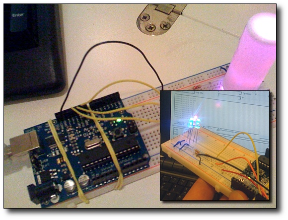
During the class period, I uploaded the assignment sample code that allows for user input through the serial port. I use a Linux operating system, and I found that cutecom was a great application to send commands to the serial port (as an alternative to the Arduino serial monitor). After I found a decent diffuser, (a perfectly sized Advil travel bottle) I used Clay Shirky's cross-fading PWM code with a delay of 5 milliseconds to make a more interesting light display.
Code used in this Assignment:
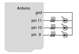
// Output
int redPin = 9; // Red LED, connected to digital pin 9
int greenPin = 10; // Green LED, connected to digital pin 10
int bluePin = 11; // Blue LED, connected to digital pin 11
// Program variables
int redVal = 255; // Variables to store the values to send to the pins
int greenVal = 1; // Initial values are Red full, Green and Blue off
int blueVal = 1;
int i = 0; // Loop counter
int wait = 5; // 5ms (.005 second) delay;
int DEBUG = 1; // DEBUG counter; if set to 1, will write values back via serial
void setup()
{
pinMode(redPin, OUTPUT); // sets the pins as output
pinMode(greenPin, OUTPUT);
pinMode(bluePin, OUTPUT);
if (DEBUG) { // If we want to see the pin values for debugging...
Serial.begin(9600); // ...set up the serial ouput on 0004 style
}
}
// Main program
void loop()
{
i += 1; // Increment counter
if (i < 255) // First phase of fades
{
redVal -= 1; // Red down
greenVal += 1; // Green up
blueVal = 1; // Blue low
}
else if (i < 509) // Second phase of fades
{
redVal = 1; // Red low
greenVal -= 1; // Green down
blueVal += 1; // Blue up
}
else if (i < 763) // Third phase of fades
{
redVal += 1; // Red up
greenVal = 1; // Green low
blueVal -= 1; // Blue down
}
else // Re-set the counter, and start the fades again
{
i = 1;
}
analogWrite(redPin, redVal); // Write current values to LED pins
analogWrite(greenPin, greenVal);
analogWrite(bluePin, blueVal);
if (DEBUG) { // If we want to read the output
DEBUG += 1; // Increment the DEBUG counter
if (DEBUG > 10) // Print every 10 loops
{
DEBUG = 1; // Reset the counter
Serial.print(i); // Serial commands in 0004 style
Serial.print("\t"); // Print a tab
Serial.print("R:"); // Indicate that output is red value
Serial.print(redVal); // Print red value
Serial.print("\t"); // Print a tab
Serial.print("G:"); // Repeat for green and blue...
Serial.print(greenVal);
Serial.print("\t");
Serial.print("B:");
Serial.println(blueVal); // println, to end with a carriage return
}
}
delay(wait); // Pause for 'wait' milliseconds before resuming the loop
}