Components
potentiometer x 2
red, green and blue LEDs
wires
arduino board and bread board
Brightness of a single LED (with one pot)
In the first part, we control the brightness of the green LED with one potentiometer.
Code
/*
* one pot fades one led
* modified version of AnalogInput
* by DojoDave <http://www.0j0.org>
* http://www.arduino.cc/en/Tutorial/AnalogInput
*/
int potPin = 0; // select the input pin for the potentiometer
int ledPin = 10; // select the pin for the LED
int val = 0; // variable to store the value coming from the sensor
void setup() {
Serial.begin(9600);
}
void loop() {
val = analogRead(potPin); // read the value from the sensor, between 0 - 1024
Serial.println(val);
analogWrite(ledPin, val/4); // analogWrite can be between 0-255
}
Demo
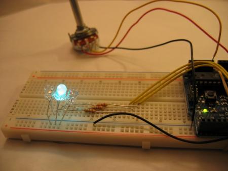
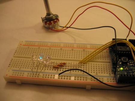
The following two pictures show the different brightness of the green LED controlled by a poteniometer.


Blinking of a single LED (with one pot)
In this part, we control the blinking rate of the green LED with one potentiometer.
Code
/*
* AnalogInput
* by DojoDave <http://www.0j0.org>
*
* Turns on and off a light emitting diode(LED) connected to digital
* pin 13. The amount of time the LED will be on and off depends on
* the value obtained by analogRead(). In the easiest case we connect
* a potentiometer to analog pin 2.
*
* http://www.arduino.cc/en/Tutorial/AnalogInput
*/
int potPin = 0; // select the input pin for the potentiometer
int ledPin = 10; // select the pin for the LED
int val = 0; // variable to store the value coming from the sensor
void setup() {
pinMode(ledPin, OUTPUT); // declare the ledPin as an OUTPUT
}
void loop() {
val = analogRead(potPin); // read the value from the sensor
digitalWrite(ledPin, HIGH); // turn the ledPin on
delay(val); // stop the program for some time
digitalWrite(ledPin, LOW); // turn the ledPin off
delay(val); // stop the program for some time
}
Demo
The following two videos show the different blinking rates controlled by a potentiometer.
video 1, video 2
Blinking and lightness of a single LED (with two pots)
In this part, we use two pots. One pot controls the brightness and the other controls the blinking rate.
Code
/*
* one pot dims, the other pot changes the blinking rate
* modification of the following
* http://www.arduino.cc/en/Tutorial/AnalogInput
*/
int pot1Pin = 0; // select the input pin for the potentiometer 1
int pot2Pin = 1; // select the input pin for the potentiometer 2
int pot1Val = 0; // variable to store the value coming from pot 1
int pot2Val = 0; // variable to store the value coming from pot 2
int led1Pin = 10; // select the pin for the LED 1
int led2Pin = 11; // select the pin for the LED 2
void setup() {
pinMode(led1Pin, OUTPUT); // declare the led1Pin as an OUTPUT
pinMode(led2Pin, OUTPUT); // declare the led2Pin as an OUTPUT
}
void loop() {
pot1Val = analogRead(pot1Pin); // read the value from pot 1, between 0 - 1024, for dimming
pot2Val = analogRead(pot2Pin); // read the value from pot 2, between 0 - 1024, for blinking
analogWrite(led1Pin, pot1Val/4); // dim LED to value from pot1
delay(pot2Val); // stop the program for some time, meaning, LED is on for this time
analogWrite(led1Pin, 0); // dim LED to completely dark (zero)
delay(pot2Val); // stop the program for some time, meaning, LED is OFF for this time
}
Three LEDs blinking in alternately(with two pots)
To make the previous part more interactive, i modify the code to make the three LEDS blink alternately (R->G->B->R->G->B->R...) Of course, the brightness and blinking is controlled by two pots.
Code
/*
* one pot dims, the other pot changes the blinking rate
* modification of the following
* http://www.arduino.cc/en/Tutorial/AnalogInput
*/
int pot1Pin = 0; // select the input pin for the potentiometer 1
int pot2Pin = 1; // select the input pin for the potentiometer 2
int pot1Val = 0; // variable to store the value coming from pot 1
int pot2Val = 0; // variable to store the value coming from pot 2
int led1Pin = 9; // select the pin for the LED 1
int led2Pin = 10; // select the pin for the LED 2
int led3Pin = 11; // select the pin for the LED 3
void setup() {
pinMode(led1Pin, OUTPUT); // declare the led1Pin as an OUTPUT
pinMode(led2Pin, OUTPUT); // declare the led2Pin as an OUTPUT
}
void loop() {
pot1Val = analogRead(pot1Pin); // read the value from pot 1, between 0 - 1024, for dimming
pot2Val = analogRead(pot2Pin); // read the value from pot 2, between 0 - 1024, for blinking
analogWrite(led1Pin, pot1Val/4); // dim LED to value from pot1
delay(pot2Val); // stop the program for some time, meaning, LED is on for this time
analogWrite(led1Pin, 0); // dim LED to completely dark (zero)
delay(pot2Val); // stop the program for some time, meaning, LED is OFF for this time
analogWrite(led2Pin, pot1Val/4); // dim LED to value from pot1
delay(pot2Val); // stop the program for some time, meaning, LED is on for this time
analogWrite(led2Pin, 0); // dim LED to completely dark (zero)
delay(pot2Val); // stop the program for some time, meaning, LED is OFF for this time
analogWrite(led3Pin, pot1Val/4); // dim LED to value from pot1
delay(pot2Val); // stop the program for some time, meaning, LED is on for this time
analogWrite(led3Pin, 0); // dim LED to completely dark (zero)
delay(pot2Val); // stop the program for some time, meaning, LED is OFF for this time
}
Demo
video
DJ-like control by potentiometers
In this part, we use the value input by a potentiometer to control which LED to blink. By turning the potentiometer, either clockwise and counter-clockwise, or fast and slow, we can control which LED to blink as if a DJ mixes music by turning a disk.
Code
/*
* one pot dims, the other pot changes the blinking rate
* modification of the following
* http://www.arduino.cc/en/Tutorial/AnalogInput
*/
int pot1Pin = 0; // select the input pin for the potentiometer 1
int pot2Pin = 1; // select the input pin for the potentiometer 2
int pot1Val = 0; // variable to store the value coming from pot 1
int pot2Val = 0; // variable to store the value coming from pot 2
int led1Pin = 9; // select the pin for the LED 1
int led2Pin = 10; // select the pin for the LED 2
int led3Pin = 11; // select the pin for the LED 3
void setup() {
pinMode(led1Pin, OUTPUT); // declare the led1Pin as an OUTPUT
pinMode(led2Pin, OUTPUT); // declare the led2Pin as an OUTPUT
}
void loop() {
pot1Val = analogRead(pot1Pin) ; // read the value from pot 1, between 0 - 1024, for dimming
pot2Val = analogRead(pot2Pin); // read the value from pot 2, between 0 - 1024, for blinking
if (pot1Val/4 < 85) {
analogWrite(led2Pin, 0); // dim LED to value from pot1
analogWrite(led3Pin, 0); // dim LED to value from pot1
analogWrite(led1Pin, 255); // dim LED to value from pot1
delay(pot2Val);
analogWrite(led1Pin, 0); // dim LED to value from pot1
delay(pot2Val);
}
else if (pot1Val/4 < 170)
{
analogWrite(led1Pin, 0); // dim LED to value from pot1
analogWrite(led3Pin, 0); // dim LED to value from pot1
analogWrite(led2Pin, 255); // dim LED to value from pot1
delay(pot2Val);
analogWrite(led2Pin, 0); // dim LED to value from pot1
delay(pot2Val);
}
else
{
analogWrite(led1Pin, 0); // dim LED to value from pot1
analogWrite(led2Pin, 0); // dim LED to value from pot1
analogWrite(led3Pin, 255); // dim LED to value from pot1
delay(pot2Val);
analogWrite(led3Pin, 0); // dim LED to value from pot1
delay(pot2Val);
}
}
Demo
video


