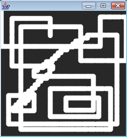
Processing Etch-A-Sketch
Description
I modified the Arduino LED fade code so that two pots control fading of
two LEDs, but also output values to the serial port. One pot outputs
values from 0-255, the other outputs values from 256-511, so that
Processing can distinguish between the two. I then modified the
Processing ball drawing code so that when the first pots is turned up
or down, Processing draws lines to the right or the left. When the
second pot is turned, Processing draws lines up or down. This creates
an effect similar to the Etch-A-Sketch toy. Pressing the spacebar
clears the screen.
Materials
Arduino board, two potentiometers, two LEDs
Arduino Code
/*
* Resistive Sensor Input
* Takes the input from a resistive sensor, e.g., FSR or photocell
* Dims the LED accordingly, and sends the value (0-255) to the serial port
*/
int sensorPin1 = 0; // select the input pin for the sensor
int ledPin1 = 10; // select the output pin for the LED
int val1 = 0; // variable to store the value coming from the sensor
int sensorPin2 = 1; // select the input pin for the sensor
int ledPin2 = 11; // select the output pin for the LED
int val2 = 0; // variable to store the value coming from the sensor
void setup() {
Serial.begin(9600);
}
void loop() {
val1 = analogRead(sensorPin1); // read the value from the sensor, 0-1023
analogWrite(ledPin1, val1/4); // analogWrite (dimming the LED) can be between 0-255
Serial.println(val1/4); // writing the value from pot 1 to the PC via serial connection
delay(10); // rest a little...
val2 = analogRead(sensorPin2); // read the value from the sensor, 0-1023
analogWrite(ledPin2, val2/4); // analogWrite (dimming the LED) can be between 0-255
Serial.println(val2/4 + 256); // writing the value from pot 2 to the PC via serial connection
delay(10); // rest a little...
}
Processing Code
/*
* Arduino Etch-a-Sketch
* (Arduino Ball, modified)
* ----------------------
*
* Takes serial input from two potentiometers. (One pot feeds values
* from 0-255, the other feeds values from 256-511.)
*
* Turning the first pot up draws a line to the right, turning the first
* pot down draws a line to the left. Turning the second pot to up draws
* a line up, while turning the second pot down draws a line down.
*
* Receives an ASCII number over the serial port,
* terminated with a carriage return (ascii 13) then newline (10).
*
* This matches what Arduino's " Serial.println(val)" function
* puts out.
*
* Created 25 October 2006
* copyleft 2006 Tod E. Kurt <tod@todbot.com
* http://todbot.com/
*
* Modified by Jonathan Breitbart 26 September 2007
*/
import processing.serial.*;
// Change this to the portname your Arduino board
String portname = "COM4"; // or "COM5"
Serial port;
String buf="";
int cr = 13; // ASCII return == 13
int lf = 10; // ASCII linefeed == 10
int x = 0;
int y = 0;
int val1;
int val2;
void setup() {
size(255,255);
frameRate(10);
smooth();
background(40,40,40);
noStroke();
port = new Serial(this, portname, 9600);
stroke(255);
strokeWeight(10);
}
void draw() {
}
// draw balls
//void drawball(int x, int y, int r) {
//for (int i=0; i<100; i++ ) {
//fill(255-i,i,240);
//ellipse(x,y,r,r);
//}
// called whenever serial data arrives
void serialEvent(Serial p) {
int c = port.read();
if (c != lf && c != cr) {
buf += char(c);
}
if (c == lf) {
int val = int(buf);
if (val < 256) { //if pot 1 gives input
val1 = val;
println("val1="+val1);
}
if (val > 255) { //if pot 2 gives input
val2 = val-256;
println("val2="+val2);
}
if (val1 > (x+5)) { //draw to the right
line(x,y,x+4,y);
x = val1;
}
if (val1 < (x-5)) { //draw to the left
line(x,y,x-4,y);
x = val1;
}
if (val2 > (y+5)) { //draw upwards
line(x,y,x,y+4);
y = val2;
}
if (val2 < (y-5)) { //draw downwards
line(x,y,x,y-4);
y = val2;
}
buf = "";
//background(40,40,40); // erase screen
}
}
void keyPressed() {
if(key == ' ') {
background(40,40,40); // erase screen
}
//else {
//int x = int(random(0,width));
//int y = int(random(0,height));
//drawball(x,y, 50);
//}
}
Sample Drawing
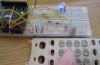
FSR Distributor
Description
For this part of the lab, I took apart an old touch-tone telephone and used
the face plate and the buttons. I then placed a soy sauce packet in
between these parts and the FSR. When each button is pressed, it shifts
the liquid in the soy sauce path, which in turn activates the FSR and
turns the light on. I used the Arduino LED fade code. I did not have
time to solder my FSR to wires, but when I do, I would like to try
embedding the FSR in the phone completely.
Materials
Arduino board, LED, FSR, phone faceplate, buttons, soy sauce packet
Sample Pictures


Comments
Nice Job! It's a hi-tech
Nice Job! It's a hi-tech etch-a-sketch! I'm a bit confused as to what the FSR did though. Could you clarify that a bit?
so, i found that a soy sauce
so, i found that a soy sauce packet was a good distributor of
force. so i wanted to use it in some context and thought about placing
the fsr in a telephone, with the soy sauce packet between it and the
buttons, so that when a button was pressed, depending on how far the
button was from the center (where the fsr was located), the LED would light up to a level corresponding to the pressure applied to the FSR. i didn't have my fsr soldered, so i couldn't embed it directly in the phone. so i didn't use the complete phone housing, just the faceplate, buttons, and soy sauce packet.