Using Potentiometers to Control LEDs
Description
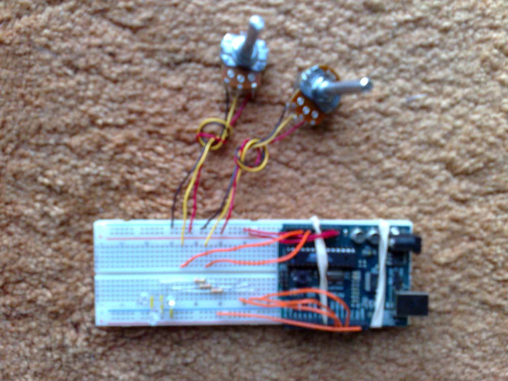
This lab uses 2 potentiometers to control 3 LEDs
Components Used
2 potentiometers
3 LEDs
3 resistors
Arduino Code
/*
* "Coffee-cup" Color Mixer:
* This program controls 3 LEDs with 3 potentiometers. One potentiometer controls two LEDs, the other controls one LED.
*/
// Analog pin settings
int aIn = 1; // Potentiometers connected to analog pins 0, 1, and 2
int bIn = 2; // (Connect power to 5V and ground to analog ground)
//int cIn = 2;
// Digital pin settings
int aOut = 9; // LEDs connected to digital pins 9, 10 and 11
int bOut = 10; // (Connect cathodes to digital ground)
int cOut = 11;
// Values
int aVal = 0; // Variables to store the input from the potentiometers
int bVal = 0;
int cVal = bVal;
// Variables for comparing values between loops
int i = 0; // Loop counter
int wait = (1000); // Delay between most recent pot adjustment and output
int checkSum = 0; // Aggregate pot values
int prevCheckSum = 0;
int sens = 3; // Sensitivity theshold, to prevent small changes in
// pot values from triggering false reporting
// FLAGS
int PRINT = 1; // Set to 1 to output values
int DEBUG = 1; // Set to 1 to turn on debugging output
void setup()
{
pinMode(aOut, OUTPUT); // sets the digital pins as output
pinMode(bOut, OUTPUT);
pinMode(cOut, OUTPUT);
Serial.begin(9600); // Open serial communication for reporting
}
void loop()
{
i += 1; // Count loop
aVal = analogRead(aIn) / 4; // read input pins, convert to 0-255 scale
bVal = analogRead(bIn) / 4;
cVal = analogRead(bIn) / 4;
analogWrite(aOut, aVal); // Send new values to LEDs
analogWrite(bOut, bVal);
analogWrite(cOut, cVal);
if (i % wait == 0) // If enough time has passed...
{
checkSum = aVal+bVal+cVal; // ...add up the 3 values.
if ( abs(checkSum - prevCheckSum) > sens ) // If old and new values differ
// above sensitivity threshold
{
if (PRINT) // ...and if the PRINT flag is set...
{
Serial.print("A: "); // ...then print the values.
Serial.print(aVal);
Serial.print("\t");
Serial.print("B: ");
Serial.print(bVal);
Serial.print("\t");
Serial.print("C: ");
Serial.println(cVal);
PRINT = 0;
}
}
else
{
PRINT = 1; // Re-set the flag
}
prevCheckSum = checkSum; // Update the values
if (DEBUG) // If we want debugging output as well...
{
Serial.print(checkSum);
Serial.print("<=>");
Serial.print(prevCheckSum);
Serial.print("\tPrint: ");
Serial.println(PRINT);
}
}
}
Image
(also see attached lab3.jpg)

Board with LEDs and pots

Comments
hey jill, in future lab
hey jill, in future lab reports, can you provide more detailed descriptions? Like what the inputs are and how the system reacts? Otherwise, nice job!
dave