Descriptions:
After being able to use 2 and 3 pots to control dimming and blinking speed of three RGB LEDs separately from the Lab 3 last week, I start to consider using one pot to discuss relationship between three LEDs. Thus, I try to use 3 pots controlling dimming, blinking speed, and lighting sequence of three RGB LEDs separately:
Pot 1 for dimming
Pot 2 for Blinking Speed
Pot 3 for Lighting Flow (sequence)
For Pot 3, to make the light “flow” between 3 LED, there are five ranges defined for making the lighting sequence similar to a circle: Blue-Green-Red-Green-Blue. When the Target LED is lighten, the dimming degree and blinking speed could be controlled by Pot 1 and Pot 2. Using higher blinking frequency and lighting strength for the Target LED could make the phenomenon of “Lighting Flow” more clearly.
For the diffuser "Mood Egg", the lighting flow indicates the insight of one's feeling consciously/ subconsciously according to various variables.
http://photo.xuite.net/berkeleychiu/2005583/4.jpg
For the diffuser "Alien Bean", the lighting flow indicates some kinds of organic transformation or evolution triggered via different cosmos.
http://photo.xuite.net/berkeleychiu/2005583/5.jpg
Components:
3 potentiometer pots, Arduino board, bread board, 3 RGB LEDs, 6 wires
Codes:
/*
*Pot 1 for dimming control, Pot 2 for blinking control, and Pot 3 for making lighting flow inbetween three LED
*modified version of AnalogInput
*by DojoDave <http://www.0j0.org>
*http://www.arduino.cc/en/Tutorial/AnalogInput
*/
int pot1Pin = 0; // select the input pin for the potentiometer 1
int pot2Pin = 1; // select the input pin for the potentiometer 2
int pot3Pin = 2; // select the input pin for the potentiometer 3
int pot1Val = 0; // variable to store the value coming from pot 1
int pot2Val = 0; // variable to store the value coming from pot 2
int pot3Val = 0; // variable to store the value coming from pot 3
int TargetLED = 11; // start from Blue LED
int RedPin = 9; // select the pin for the Red LED
int GreenPin = 10; // select the pin for the Green LED
int BluePin = 11; // select the pin for the Blue LED
void setup() {
Serial.begin(9600);
pinMode(RedPin, OUTPUT); // declare the RedPin as an OUTPUT
pinMode(GreenPin, OUTPUT); // declare the GreenPin as an OUTPUT
pinMode(BluePin, OUTPUT); // declare the BluePin as an OUTPUT
}
void loop() {
pot1Val = analogRead(pot1Pin); // read the value from pot 1, between 0 - 1024, for dimming
pot2Val = analogRead(pot2Pin); // read the value from pot 2, between 0 - 1024, for blinking
pot3Val = analogRead(pot3Pin); // read the value from pot 3, between 0 - 1024, to select output LED
Serial.println(pot1Val);
//To make the light flow between 3 LED, there are five ranges starting from B-G-R-G-B as smiliar to a circle
if (pot3Val > 801) TargetLED = 11; // the range 801 - 1024 is for Green LED
else if (pot3Val > 601) TargetLED = 10; // the range 601 - 800 is for Green LED
else if (pot3Val > 401) TargetLED = 9; // the range 401 - 600 is for Red LED
else if (pot3Val > 201) TargetLED = 10; // the range 201 - 400 is for Green LED
else TargetLED = 11; // the range 0 - 200 is for Blue LED
analogWrite(TargetLED, pot1Val/4); // light the selected LED
delay(pot2Val); // stop the program for some time, meaning, LED is on for this time
analogWrite(TargetLED, 0); // dim LED to completely dark (zero)
delay(pot2Val); // stop the program for some time, meaning, LED is OFF for this time
}
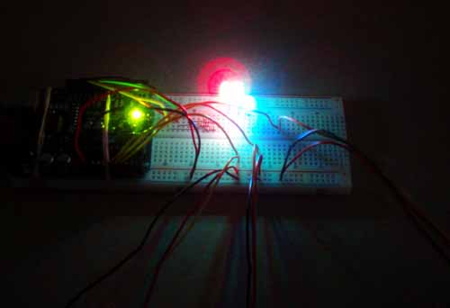
Image Description:
The picture atttached is shot with B-Carema shetter in the dark to show the "lighting flow" between three RGB LEDs.
http://photo.xuite.net/berkeleychiu/2005583/3.jpg
http://photo.xuite.net/berkeleychiu/2005583/1.jpg
http://photo.xuite.net/berkeleychiu/2005583/2.jpg

Comments
producing consistently nice
producing consistently nice work, hsin-hsien. Keep it up!