Description
I finished two exercises during the two-hour lab, using single pot controls brightness, and using one pot controls blinking and the other controls brightness. I also finish the three pots control the brightness of three LEDs at home, and the potentiometers worked very well. It really was an interesting experience.
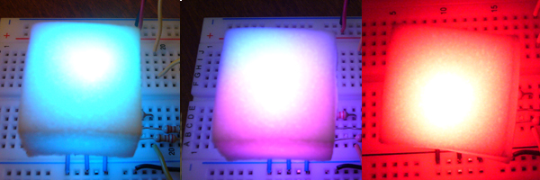
For the home work, I recalled my experience of selecting colors in Photoshop by applying a slider, so I decided to copy this feature into my LED set. On one hand, instead of using the code provided by the course website, I wrote code to implement PWM to control brightness. I set the period to 10ms and use one pot to control the amount of time during that period LEDs are on. To implement the slider feature, I create a function that converts HSB to RGB value based on the transformation formula at http://en.wikipedia.org/wiki/HSV_color_space. There are actually three values that I can change but I only used the second pot to control the hue value. I set both saturation and brightness to 1 (their maximum value).
At the beginning, for some reason, the code didn’t work very well. Since I don’t have much experience in debugging, I asked my friend to help. He found out that it is necessary to set some variables as type float to avoid integer overflow and to avoid rounding errors. After these fixes, the code works!!! I've left the debugging code below since it was instrumental at fixing the code.
Component
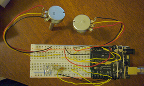
- Arduino board
- White breadboard
- Three LED (the red one connects to pin11, the green one connects to pin9, and the blue one connects to pin10)
- Three 220-OHM resistors (labeled as red-red-brown-gold)
- Wires connect LED to Arduino board (black and 3 short blue ones connect to ground, and 3 yellow connect LEDs and the resistors to pin 9, 10, 11)
- 2 potentiometer with wires soldered on
- Wires connect potentiometer to Arduino board (black ones connect to ground, red ones connects to 5V, and yellow ones connect to pin 0 and 1 )
- 2 rubber bands
- USB cable
- Arduino environment
Code
/*
* Use one potentiometer to control BRIGHTNESS, and the other to control the Hue Value
* Brightness-> Control PWM
* Hue Value-> Contver to RGB
*/
// Debug flag
int DEBUG = 0;
int i = 0; // loop counter
// Potentiameter pin settings; analog inputs; value ranges from 0 - 1023
int aIn = 0; // Control LED Blinkging PWM
int bIn = 1; // Control Hue Value
// Digital pin settings
int rOut = 11; // goes to Red LED
int gOut = 9; // goes to Green LED
int bOut = 10; // goes to Blue LED
// Values
int aVal = 0; // Variables to store the input from the potentiometer
int bVal = 0;
int period = 10; // period of the PWM, millisecond
float hue; // Hue Value
int R, G, B;
void HSB2RGB(float h, float s, float v){ //formula of converting Hue Value to RGB
float f, p, q, t, r, g, b;
int hi;
hi = int(h/60);
f = h/60-hi;
p = v*(1-s);
q = v*(1-f*s);
t = v*(1-(1-f)*s);
switch (hi){
case 0: r = v; g = t; b = p; break;
case 1: r = q; g = v; b = p; break;
case 2: r = p; g = v; b = t; break;
case 3: r = p; g = q; b = v; break;
case 4: r = t; g = p; b = v; break;
case 5: r = v; g = p; b = q; break;
default: r = 1.0; g = 1.0; b = 1.0;
}
// debugging output
if (DEBUG) {
if (i % 200 == 0) { // print the value of B every second
Serial.print("r = ");
Serial.print((int)r*1000);
Serial.print(", g = ");
Serial.print((int)g*1000);
Serial.print(", b = ");
Serial.println((int)b*1000);
}
}
R=r*255; G=g*255; B=b*255;
} // end HSB2RGB()
void setup() {
pinMode(rOut, OUTPUT);
pinMode(gOut, OUTPUT);
pinMode(bOut, OUTPUT);
Serial.begin(9600);
}
void loop() {
float lowtime, hightime;
i++;
aVal = analogRead(aIn); //read the value from pot 0, between 0 - 1024, for blinking
bVal = analogRead(bIn);
hue = (float)bVal*360/1024;
hightime = (float)aVal*period/1024;
lowtime = period - hightime;
HSB2RGB(hue, 1.0, 1.0);
analogWrite(rOut, R);
analogWrite(gOut, G);
analogWrite(bOut, B);
delay((int)hightime); // stop the program for some time
digitalWrite(rOut, LOW); // turn the LEDs off
digitalWrite(gOut, LOW);
digitalWrite(bOut, LOW);
delay((int)lowtime); // stop the program for some time
// debugging output
if (DEBUG) {
if (i % 200 == 0) { // print the value every 2 seconds
Serial.print("aIn = ");
Serial.print(aVal);
Serial.print(", bIn = ");
Serial.print(bVal);
Serial.print(", hue = ");
Serial.print((int)hue);
Serial.print(", R = ");
Serial.print(R);
Serial.print(", G = ");
Serial.print(G);
Serial.print(", B = ");
Serial.println(B);
}
}
} // end loop()
Photograph

Comments
nice work! Good sleuthing
nice work! Good sleuthing with the code and i'm glad to hear the process you went through to get this thing working. From the photos, it looks like it was totally worth it. nice use of the switch statement in your code. not bad for someone who "doesn't have much experience" :P