Description: Here the arduino board is fastened to a breadboard via rubber bands, and the circuit is wired to connect three differently colored LED lights to the three PWM (Pulse Width Modulation) pins on the arduino (this is an extension of last week's project). After the circuit is made, a pulse ("fading") program is uploaded to the arduino board and a filter is added to diffuse the light.
Components Used:
(1) Breadboard; Arduino Board; bottle cap; usb wire; black ground wire
(2) Rubber Bands
(3) 220-ohm resistors; yellow wires feeding the resistors; blue wires grounding the LEDs; Differently-colored LEDs
(4) Q-tips
(some) Mounting Putty
Code:
This is the code from the website that was running in the posted images, though the serial codes were later implemented.
// Output
int redPin = 9; // Red LED, connected to digital pin 9
int greenPin = 10; // Green LED, connected to digital pin 10
int bluePin = 11; // Blue LED, connected to digital pin 11
// Program variables
int redVal = 255; // Variables to store the values to send to the pins
int greenVal = 1; // Initial values are Red full, Green and Blue off
int blueVal = 1;
int i = 0; // Loop counter
int wait = 50; // 50ms (.05 second) delay; shorten for faster fades
int DEBUG = 0; // DEBUG counter; if set to 1, will write values back via serial
void setup()
{
pinMode(redPin, OUTPUT); // sets the pins as output
pinMode(greenPin, OUTPUT);
pinMode(bluePin, OUTPUT);
if (DEBUG) { // If we want to see the pin values for debugging...
Serial.begin(9600); // ...set up the serial ouput on 0004 style
}
}
// Main program
void loop()
{
i += 1; // Increment counter
if (i < 255) // First phase of fades
{
redVal -= 1; // Red down
greenVal += 1; // Green up
blueVal = 1; // Blue low
}
else if (i < 509) // Second phase of fades
{
redVal = 1; // Red low
greenVal -= 1; // Green down
blueVal += 1; // Blue up
}
else if (i < 763) // Third phase of fades
{
redVal += 1; // Red up
greenVal = 1; // Green low
blueVal -= 1; // Blue down
}
else // Re-set the counter, and start the fades again
{
i = 1;
}
analogWrite(redPin, redVal); // Write current values to LED pins
analogWrite(greenPin, greenVal);
analogWrite(bluePin, blueVal);
if (DEBUG) { // If we want to read the output
DEBUG += 1; // Increment the DEBUG counter
if (DEBUG > 10) // Print every 10 loops
{
DEBUG = 1; // Reset the counter
Serial.print(i); // Serial commands in 0004 style
Serial.print("\t"); // Print a tab
Serial.print("R:"); // Indicate that output is red value
Serial.print(redVal); // Print red value
Serial.print("\t"); // Print a tab
Serial.print("G:"); // Repeat for green and blue...
Serial.print(greenVal);
Serial.print("\t");
Serial.print("B:");
Serial.println(blueVal); // println, to end with a carriage return
}
}
delay(wait); // Pause for 'wait' milliseconds before resuming the loop
}
Visual Documentation:
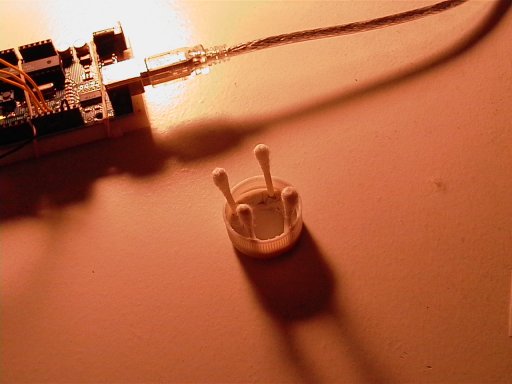
There She Be: Diffuser: bottle cap fitted with q-tips via mounting putty
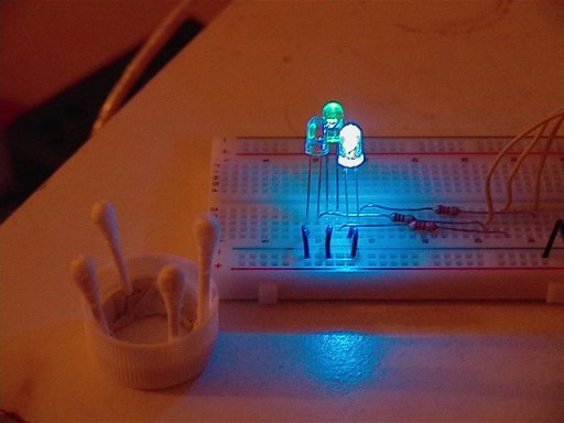
Redundancy: LED sans diffuser = lame
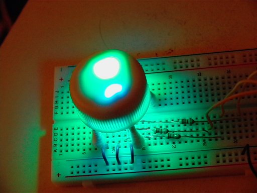
Close Encounters
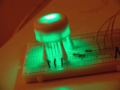
In My Room, Lights Off



Comments
GSI Comments
I like your diffuser! The interaction with the different densities of plastic inside of the bottlecap is cool, as is the ring of reflected light that comes out the bottom. It looks a little anthropomorphic, which might be a fun idea to play with.