Description
Results of questions 2 and 3 from Homework.
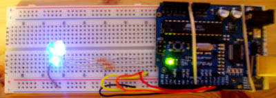
3 was to build the circuit and adapt the code provided on-line to change the LED brightness level using keystrokes.
2 was to build a diffusor so that the color mixing effects might be more easily observed.
Notes
Though I have little experience, I enjoy building the circuits and find this very intuitive.
I can honestly say that this was the first time I have ever grasped what writing code means - it is not intuitive at all to me. I am learning the function of various terms and general formatting issues by going through the code, looking up the terms on the arduino page, and by trial and error.
Building the diffusor was interesting. There is a trade-off between diffusion and overall brightness. However, as the eye is better at distinguishing colors from a background than mixing the sensory inputs together, I took the challenge as being to create a perfectly flat color field. This also involves directing the viewer's eye - the diffusion only works from one angle.
Components of diffusor
toilet paper tube, toilet paper, garlic skin, white plastic bag material, rubber band, electrical tape, clear glue, scissors, exacto knife, pencil.
Procedure (simplified)
Cut tube into three smaller tubes.
Cut 8 half-inch notches in one side of two of the tubes, and squeeze them together to reduce the diameter so the tubes nest like reeds (the segmented plants).
Cut three-quarter inch (-) diameter circle from garlic skin and glue it onto the center of a three-inch circular piece of toilet paper. This is to increase the diffusion at the center.
Place this circle on top of the bottom cylinder, and press the second cylander onto it to fix it in place.
Cut a three-quarter inch (+) diameter circle from plastic bag and glue to the center of a three inch piece of plastic bag.
This peice goes between cylindars 2 and 3.
Finally, affix a second 3 inch diameter peice of plastic to the top surface of the tube using a rubber band.
The weakness of this design is that it wastes a lot of light.
The strength is that the light is very even.
Components of circuit
arduino board, breadboard, 3 LEDs, 3, 220-OHM resistors, various wires, elastic bands, USB cable, arduino software.
Code
/*
* Serial RGB LED
* ---------------
* Serial commands control the brightness of R,G,B LEDs
*
* Command structure is "<colorCode><colorVal>", where "colorCode" is
* one of "r","g",or "b" and "colorVal" is a number 0 to 255.
* E.g. "r0" turns the red LED off.
* "g127" turns the green LED to half brightness
* "b64" turns the blue LED to 1/4 brightness
*
* Alternate command structure is "<colorCode>*", where "colorCode" is
* one of "r","g", or "b".
* E.g. "r" increases the red LED brightness by 10
* "rrr" increases the red LED brightness by 30
* "ggb" increases the green LED brightness by 20 and the blue by 10
*
* Created 18 October 2006
* copyleft 2006 Tod E. Kurt <tod@todbot.com
* http://todbot.com/
*
* Adapted 5 September 2007
* copylefter 2007 Ryan Aipperspach <ryanaip@alumni.rice.edu>
*
*/
//include support for manipulating strings.
//for a useful string comparison function, see the bottom of this file... stringsEqual()
#include <stdio.h>
#include <string.h>
char serInString[100]; // array that will hold the different bytes of the string. 100=100characters;
// -> you must state how long the array will be else it won't work properly
char colorCode;
int redPin = 9; // Red LED, connected to digital pin 9
int greenPin = 10; // Green LED, connected to digital pin 10
int bluePin = 11; // Blue LED, connected to digital pin 11
int redValue = 127;
int greenValue = 127;
int blueValue = 127;
void setup() {
pinMode(redPin, OUTPUT); // sets the pins as output
pinMode(greenPin, OUTPUT);
pinMode(bluePin, OUTPUT);
Serial.begin(9600);
analogWrite(redPin, redValue); // set them all to mid brightness
analogWrite(greenPin, greenValue); // set them all to mid brightness
analogWrite(bluePin, blueValue); // set them all to mid brightness
Serial.println("enter color command as r's b's and g's :");
}
void loop () {
//read the serial port and create a string out of what you read
readSerialString(serInString, 100);
//reads commands of the form 'rrrb'
processRepeatKeyCommands(serInString, 100);
//Erase anything left in the serial string, preparing it for the
//next loop
resetSerialString(serInString, 100);
delay(100); // wait a bit, for serial data
}
void resetSerialString (char *strArray, int length) {
for (int i = 0; i < length; i++) {
strArray[i] = '\0';
}
}
//read a string from the serial and store it in an array
//you must supply the array variable
void readSerialString (char *strArray, int maxLength) {
int i = 0;
if(!Serial.available()) {
return;
}
while (Serial.available() && i < maxLength) {
strArray[i] = Serial.read();
i++;
}
}
//go through the string, and increase the red value for each 'r',
//the green value for each 'g', and the blue value for each 'b'.
//For example "rrrg" increases red by 30 and green by 10.
void processRepeatKeyCommands(char *strArray, int maxLength) {
int i = 0;
//loop through the string (strArray)
//i = the current position in the string
//Stop when either (a) i reaches the end of the string or
// (b) there is an empty character '\0' in the string
while (i < maxLength && strArray[i] != '\0') {
//Read in the character at position i in the string
colorCode = serInString[i];
//If the character is r (red)...
if (colorCode == 'r') {
//Increase the current red value by 10, and if you reach 255 go back to 0
redValue = (redValue + 10) % 255;
analogWrite(redPin, redValue);
Serial.print("setting color r to ");
Serial.println(redValue);
//If the character is g (green)...
} else if (colorCode == 'g') {
greenValue = (greenValue + 10) % 255;
analogWrite(greenPin, greenValue);
Serial.print("setting color g to ");
Serial.println(greenValue);
//If the character is b (blue)...
} else if (colorCode == 'b') {
blueValue = (blueValue + 10) % 255;
analogWrite(bluePin, blueValue);
Serial.print("setting color b to ");
Serial.println(blueValue);
}
//Move on to the next character in the string
//From here, the code continues executing from the "while" line above...
i++;
}
}
//compare two strings to see if they are equal
//compares the first 'numCharacters' characters of string1 and string2 to
//see if they are the same
//
//E.g. stringsEqual("hello","hello",5) => true
// stringsEqual("hello","helaabbnn",3) => true
// stringsEqual("hello","helaa",5) => false
boolean stringsEqual(char *string1, char *string2, int numCharacters) {
if (strncmp(string1, string2, numCharacters) == 0) {
return true;
} else {
return false;
}
}

Comments
GSI Comments
Really nice work! The description of your process is great, because it helps us to understand both how and why you did things. Keep up the good work.
I agree that writing code is a tricky thing to learn. But, once you have the skill, it's really helpful and gives you a lot of expressive power when working with the arduino and various transducers. Definitely let us know if we can help with anything.
I also agree that building circuits is a lot of fun! Given that you like circuits, one thing to consider is working with Max/MSP and Arduino. There's some more information on the Arduino website.