Assignment: Servo Motor: Actuation Assignment 2
Collaborators:
Assignment: Servo Motor: Actuation Assignment 2
Collaborators: Michael Manoochehri
Description:
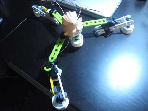
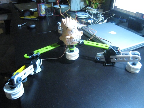
The Octo(Tri)pus Roomba Man has three servos attached to a body at (about) 180 degrees apart. Two of the servos are connected to "arms" that move in opposite directions from each other. The rear servo is connected to a "tail" that moves a little less vigorously than the arms. The servos get input from a single potentiometer, but each one processes the input differently, which produces different arm motions. Although the robot's motion is fairly erratic, it does move laterally across the floor.
Notes:
We initially tried feeding the servos random numbers for position values, which resulted in some erratic movements. We found that the robot would not move very much with this method. After trying various loops and other ways to control the robot programatically, we decided to go back to potentiometer input, as it gave us better movement control.
Our project used relatively large Erector set pieces for structure. The servo motors had high enough torque to move the pieces, but they were difficult to attach to the servo "arms." We initially used wires to tie them down, but we found the best way to make a strong (and non-permanent) attachment was by using lots and lots of electrical tape.
Another challenge we faced was in getting the legs to move in a way that could produce a consistent lateral motion. In the current configuration, each servo moves in a slightly different motion. With extra servos, we could add "shoulders" to each of the arms, possibly allowing the robot to crawl forward by moving the entire body forward, and then having the arms rotate forward to initiate the next motion.
Components:
Erector Set wheels, screws, bolts, and levers
Lots of electrical tape and wires
One potentiometer
One 10-kohm resistor
Squishy head
Three metal plates
Photos:
Video
Code
~~~~~~~~~~~~~~~~~~~~~~~~~~~~~~~~~~~~~~~~
/*
* 3 Servos with single Potentiometer Control
* Carol Chen and Michael Manoochehri
*
* BASED ON: Servo with Potentiometer control
* Theory and Practice of Tangible User Interfaces
* October 11 2007
* Provided by i290-4 Instructors
*/
int servoPin1 = 7; // Control pin for servo motor 1
int servoPin2 = 8; // Control pin for servo motor 2
int servoPin3 = 9; // Control pin for servo motor 3
int potPin = 0; // select the input pin for the potentiometer
int pulseWidth1 = 0; // Amount to pulse servo 1
int pulseWidth2 = 0; // Amount to pulse servo 2
int pulseWidth3 = 0; // Amount to pulse servo 3
long lastPulse = 0; // the time in millisecs of the last pulse
int refreshTime = 20; // the time in millisecs needed in between pulses
/*
* NOTE: WE created 3 variables here in anticipation of
* eventually using 3 potentiometers, but as you can see below,
* they each get set to the single potentiometer value.
*
*/
int val1; // variable used to store data from potentiometer
int val2; // variable used to store data from potentiometer
int val3; // variable used to store data from potentiometer
int minPulse = 700; // minimum pulse width
void setup() {
pinMode(servoPin1, OUTPUT); // Set servo pin as an output pin
pinMode(servoPin2, OUTPUT); // Set servo pin as an output pin
pinMode(servoPin3, OUTPUT); // Set servo pin as an output pin
pulseWidth1 = minPulse; // Set the motor position to the minimum
Serial.begin(9600); // connect to the serial port
Serial.println("servo_serial_better ready");
}
void loop() {
// read the value from the sensor, between 0 - 1024
// Sets each servo value to the pot pin input, but
// We can edit this to add new inputs...
val1 = analogRead(potPin);
val2 = analogRead(potPin);
val3 = analogRead(potPin);
// "TAIL" movement
if (val1 > 0 && val1 <= 999 ) {
pulseWidth1 = val1 + minPulse; // convert angle to microseconds
Serial.print("Tail: ");
Serial.println(val1);
}
// "RIGHT ARM" Movement
if (val2 > 0 && val2 <= 999 ) {
val2 = 800 - val3;
pulseWidth2 = val2*2+ minPulse; // convert angle to microseconds
Serial.print("Right Arm: ");
Serial.println(val2);
}
// "LEFT ARM" Movement
if (val3 > 0 && val3 <= 999 ) {
pulseWidth3 = val3*2 + minPulse; // convert angle to microseconds
Serial.print("Left Arm: ");
Serial.println(val3);
}
updateServo(); // update servo position
}
// called every loop().
void updateServo() {
// pulse the servo again if the refresh time (20 ms) has passed:
if (millis() - lastPulse >= refreshTime) {
digitalWrite(servoPin1, HIGH); // Turn the servo motor #1 on
delayMicroseconds(pulseWidth1); // Length of the pulse sets the
motor position
digitalWrite(servoPin1, LOW); // Turn the servo motor #1 off
digitalWrite(servoPin2, HIGH); // Turn the servo motor #2 on
delayMicroseconds(pulseWidth2); // Length of the pulse sets the
motor position
digitalWrite(servoPin2, LOW); // Turn the servo motor #2 off
digitalWrite(servoPin3, HIGH); // Turn the servo motor #3 on
delayMicroseconds(pulseWidth3); // Length of the pulse sets the
motor position
digitalWrite(servoPin3, LOW); // Turn the servo motor #3 off
lastPulse = millis(); // save the time of the last pulse
}
}