Assignment: Sensing PART II: Force sensors and photocells
Collaborators:
The purpose of this lab was to:
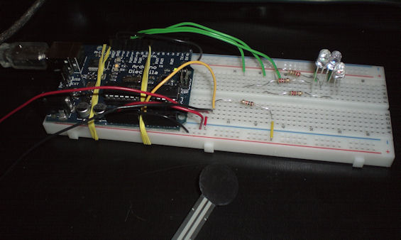
I decided to create a piggy bank out of an old medicine bottle and a mason jar to distribute weight across the force resistive sensor, and use Processing to visualize how full or empty the piggy bank was.
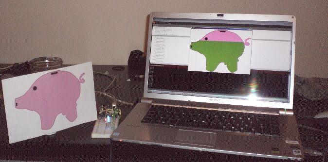
The more coins that are added to the jar, the fuller the piggy bank appears on the screen.
/* I used the same Arduino code as I used in Lab 3 when I made a color mixed with Potentiometers. */

// Analog pin settings
int aInRed   = 0;    // Potentiometers connected to analog pins 0, 1, and 2
int bInGreen = 1;    //   (Connect power to 5V and ground to analog ground)
int cInBlue  = 2;

// Digital pin settings
int aOutRed   = 9;   // LEDs connected to digital pins 9, 10 and 11
int bOutGreen = 10;  //   (Connect cathodes to digital ground)
int cOutBlue  = 11;

// Values
int aValRed   = 0;   // Variables to store the input from the potentiometers
int bValGreen = 0;
int cValBlue  = 0;

// Variables for comparing values between loops
int i = 0;            // Loop counter
int wait = (1000);    // Delay between most recent pot adjustment and output

int checkSum     = 0; // Aggregate pot values
int prevCheckSum = 0;
int sens         = 3; // Sensitivity theshold, to prevent small changes in
                      // pot values from triggering false reporting
// FLAGS
int PRINT = 1; // Set to 1 to output values
int DEBUG = 1; // Set to 1 to turn on debugging output

void setup()
{
  pinMode(aOutRed, OUTPUT);   // sets the digital pins as output
  pinMode(bOutGreen, OUTPUT);
  pinMode(cOutBlue, OUTPUT);
  Serial.begin(9600);     // Open serial communication for reporting
}

void loop()
{

  i += 1; // Count loop

  aValRed = analogRead(aInRed) / 4;  // read input pins, convert to 0-255 scale
  bValGreen = analogRead(bInGreen) / 4;
  cValBlue = analogRead(cInBlue) / 4;

  analogWrite(aOutRed, aValRed);    // Send new values to LEDs
  analogWrite(bOutGreen, bValGreen);
  analogWrite(cOutBlue, cValBlue);

   Serial.println(aValRed);

  if (i % wait == 0)                // If enough time has passed...
  {
    checkSum = aValRed+bValGreen+cValBlue;      // ...add up the 3 values.
    if ( abs(checkSum - prevCheckSum) > sens )   // If old and new values differ
                                                  // above sensitivity threshold
    {
      if (PRINT)                    // ...and if the PRINT flag is set...
      {
        /*Serial.print("A (Red): ");        // ...then print the values.
        Serial.print(aValRed);
        Serial.print("\t");
        Serial.print("B (Green): ");
        Serial.print(bValGreen);
        Serial.print("\t");
        Serial.print("C: (Blue): ");
        Serial.println(cValBlue);
        */
        PRINT = 0;
      }
    }
    else
    {
      PRINT = 1;  // Re-set the flag
    }
    prevCheckSum = checkSum;  // Update the values

    if (DEBUG)   // If we want debugging output as well...
    {
      Serial.print(checkSum);
      Serial.print("<=>");
      Serial.print(prevCheckSum);
      Serial.print("\tPrint: ");
      Serial.println(PRINT);
    }
  }
}
This code dynamically switches piggy bank images depending on the pressure applied to the force sensor. The more force, the more "full" the piggy bank is, and the more green it will be shaded.

import processing.serial.*;
// Change this to the portname your Arduino board
String portname = "COM4"; // or "COM5"
Serial port;
String buf="";
int cr = 13;  // ASCII return   == 13
int lf = 10;  // ASCII linefeed == 10

int xVal = 200;
int yVal = 420;
PImage P0;
PImage P1;
PImage P2;
PImage P3;
PImage P4;
PImage P5;
PImage P6;
PImage P7;
PImage P8;

void setup() {
  //initialize canvas:
  size(701,498);
  frameRate(10);
  smooth();
  background(40,40,40);
  noStroke();
  port = new Serial(this, portname, 9600);

  //Initialize the piggy bank images:
  P0 = loadImage("P0.gif");
  P1 = loadImage("P1.gif");
  P2 = loadImage("P2.gif");
  P3 = loadImage("P3.gif");
  P4 = loadImage("P4.gif");
  P5 = loadImage("P5.gif");
  P6 = loadImage("P6.gif");
  P7 = loadImage("P7.gif");
  P8 = loadImage("P8.gif");
  background(P0);

  //image(piggyBank, 0, 0);

}
void draw() {
}

// called whenever serial data arrives
void serialEvent(Serial p) {
  int c = port.read();
  if (c != lf && c != cr) {
    buf += char(c);
  }
  if (c == lf) {
    int val = int(buf);
    println("val="+val);
    buf = "";
    //background(40,40,40);  // erase screen
    float n = 1.0; //sensitivity factor
    if(val < 50/n)
       background(P0);
    else if(val < 75/n)
       background(P1);
    else if(val < 100/n)
       background(P2);
    else if(val < 125/n)
       background(P3);
    else if(val < 150/n)
       background(P4);
    else if(val < 175/n)
       background(P5);
    else if(val < 200/n)
       background(P6);
    else if(val < 225/n)
       background(P7);
    else
       background(P8);
  }
}