Assignment: Sensing PART II: Force sensors and photocells
Collaborators:

 Description:
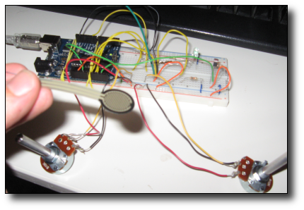
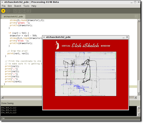
After playing with 2 potentiometers, I felt compelled to create a virtual Etch-A-Sketch type program using the Processing programming environment. The program takes values corresponding to resistances from the Arduino board, and translates those to coordinates on the screen. The circuit setup is simple - two variable resistors, one controls vertical coordinates, and the other controls horizontal. A Force Sensitive Resistor controls the color of the Etch-iSketch, the softer one presses, the "redder" the color, and the harder one presses, the "bluer" the color gets.
Components List:
Notes:
The circuitry of the board is very simple - two potentiometers, a photocell and an FSR attached to the analog inputs of the Arduino board. The pseudo Etch-a-Sketch style of the program window was created by drawing one red 500 X 412 rectangle, and then one 360 X 262 gray rectangle in the center of the larger one. The drawing output is limited to the area in the grey rectangle. Activating the photocell causes the screen to clear.
I took the potentiometer resistances and divided them by 2 to keep them roughly in the 0 to 500 range (which is the size of my program's window). Since Processing can only read input from the serial port one character at a time, resistance values from the four inputs must be output in some delimited way. I decided to output the resistance data to the serial port in this form: "x-cord,y-cord,colortoggle,clearscreen,|" I used the "|" (pipe) character as an "end of line" character. Note: I added a second comma after the "clearscreen," otherwise, I could not get the Processing environment to properly split the coordinates into an array.
The FSR sends values roughly between 0 to 1000 (but I limit it to about 750 in software.) If the FSR is pressed softly, it makes the Etch-iSketch draw red, but if one presses harder, it turns green, and then blue.
Future Work:
It would be great to make the system actually look like more like a real Etch-a-Sketch, with a shake function, wheels that move when the pots move, etc. Maybe even a "save" your image function!
Java builds for this assignment for Linux/Mac/Win can be found in this zip file (1.5 MB).
Code used in this Assignment:
Arduino Code:
/*
*  Virtual Psuedo Etch-a-Sketch
*  Etch-a-Sketch AnalogInput
*
* Pot 1: UP and DOWN
* Pot 2: LEFT and RIGHT
*
* version 0.2
* October 1, 2008
*/

// Analog pin settings
int aIn = 0;    // Potentiometers connected to analog pins 0, 1, and 2
int bIn = 1;    //   (Connect power to 5V and ground to analog ground)
int cIn = 2;
int dIn = 3;

// Digital pin settings
// YOU CAN USE THESE FOR SOME KIND OF VISUAL OUTPUT ON THE BOARD
int aOut = 9;   // LEDs connected to digital pins 9, 10 and 11
int bOut = 10;  //   (Connect cathodes to digital ground)


// Values
int aVal = 0;   // Variables to store the input from the potentiometers
int bVal = 0;
int cVal = 0;
int dVal = 0;


// Variables for comparing values between loops
int i = 0;            // Loop counter
int wait = (100);    // Delay between most recent pot adjustment and output

int checkSum     = 0; // Aggregate pot values
int prevCheckSum = 0;
int sens         = 3; // Sensitivity theshold, to prevent small changes in
// pot values from triggering false reporting

// FLAGS
int PRINT = 0; // Set to 1 to output values
int DEBUG = 0; // Set to 1 to turn on debugging output

void setup() {
pinMode(aOut, OUTPUT);   // sets the digital pins as output
pinMode(bOut, OUTPUT);
Serial.begin(9600);     // Open serial communication for reporting

}


void loop()
{
  i += 1; // Count loop
  aVal = analogRead(aIn) / 2;  // read input pins, convert to 0-500 scale

  // Set the minimum amount of "A" to 70
  if (aVal < 70) {
    aVal = 70;
  }

  // Set the maximum amount of "A" to 430
  if (aVal > 430) {
    aVal = 430;
  }

  // Reads Potentiometer 2
  bVal = analogRead(bIn) / 2;

  // Set the minimum amount of "B" to 70
  if (bVal < 70) {
    bVal = 70;
  }

  // Set the maximum amount of "B" to 332
  if (bVal > 332) {
    bVal = 332;
  }

  // Reads the FSR
  cVal = analogRead(cIn);

  if (cVal > 750) {
    cVal = 750;
  }


  // Reads PHOTOCELL
  dVal = analogRead(dIn);
  if (dVal < 30) {
    analogWrite(aOut, 100);
  } else {
    analogWrite(aOut, 0);
  }


  Serial.print(aVal);
  Serial.print(",");
  Serial.print(bVal);
  Serial.print(",");
  Serial.print(cVal);
  Serial.print(",");
  Serial.print(dVal);
  Serial.println(",|");


  if (i % wait == 0)                // If enough time has passed...
  {
    checkSum = aVal+bVal+cVal;      // ...add up the 3 values.
    if ( abs(checkSum - prevCheckSum) > sens )   // If old and new values differ
    // above sensitivity threshold
    {
      if (PRINT)  // ...and if the PRINT flag is set...
      {
       Serial.print("horizontal: ");        // ...then print the values.
       Serial.print(aVal);
       Serial.print("\t");
       Serial.print("vertical: ");
       Serial.print(bVal);
       Serial.print("\t");
       PRINT = 0;
      }
     }
   else
   {
    PRINT = 1;  // Re-set the flag
   }
   prevCheckSum = checkSum;  // Update the values

   if (DEBUG)   // If we want debugging output as well...
   {
     Serial.print(checkSum);
     Serial.print("<=>");
     Serial.print(prevCheckSum);
     Serial.print("\tPrint: ");
     Serial.println(PRINT);
   }
  }
}
Processing Code:
/*
 * Virtual Psuedo Etch-a-Sketch
 * Using the Processing Programming Environment
 *
 * Michael Manoochehri
 *
 * version 0.2
 * October 1, 2008
 *
 */

// Import processing serial library
import processing.serial.*;

// Change this to the USB Port your Arduino board
// On Linux it's usually ttyUSB0, ttyUSB1, ttyUSB2 etc...
String portname = "/dev/ttyUSB0";

Serial port; // Variable to hold the serial object
String buf="";
int var1 = 250; // Set to a value for a starting point (x-coordinate)
int var2 = 200; // Set to a value for a starting point (y-coordinate)
int var3 = 0; // Does the system draw or not?
int var4 = 200; // If this dips below 30 erase the screen!
int drawcolor = 0; // What color is the drawing?

void setup() {
  size(500,412); //Size of the program window...
  frameRate(15);
  smooth();


  // Draw the initial Red background
  // (RGB values R:187, B:0, G:0)
  // Taken from Etch a Sketch jpeg from web!
  fill(187,0,0);
  beginShape();
  vertex(0, 0);
  vertex(500, 0);
  vertex(500, 412);
  vertex(0, 412);
  endShape(CLOSE);

  PImage b;
  b = loadImage("header.gif");
  image(b, 50, 5);

  // Draw the center grey drawing surface
  // (RGB values R:228, B:228, G:228)
  // Taken from Etch a Sketch jpeg from web!
  fill(228,228,228);
  beginShape();

  vertex(70, 70);
  vertex(430, 70);
  vertex(430, 332);
  vertex(70, 332);
  endShape(CLOSE);

  // Set the port object to 9600 baud
  port = new Serial(this, portname, 9600);

  // Sets the point drawing color to BLACK
  stroke(drawcolor);
}


// I don't know if I really need this function or not
void draw() {
}


// Serial Event function:
// called whenever serial data arrives
//read the message in Processing
void serialEvent(Serial p){

String myString = port.readStringUntil(124); //the ascii value of the "|" character
  if(myString != null ){

    // This splits the string on commas into the inputs[] array
    myString = trim(myString);
    int inputs[] = int(split(myString, ','));

   // Set the x-coord value
   var1 = inputs[0];

   // Set the y-coord value
   var2 = inputs[1];

   // Set the drawcolor toggle value
   var3 = inputs[2];

   // Set the erase toggle value
   var4 = inputs[3];

   if (var4 < 30) {
     // Redraw the center rectangle
     fill(228,228,228);
     beginShape();
     vertex(70, 70);
     vertex(430, 70);
     vertex(430, 332);
     vertex(70, 332);
     endShape(CLOSE);
   }


   if (var3 < 50) {

     if (drawcolor > 0) {
        drawcolor = 0;
        stroke(drawcolor);
     }

     // Place a point at the (x,y) coordinate...
     point(var1, var2);
   } else {
     if (var3 < 255) {
       drawcolor = var3;
       stroke(drawcolor,0,0);
       print("red: ");
       println(drawcolor);
      }

      if (var3 > 255 && var3 < 510) {
       drawcolor = var3 - 254;
       stroke(0,round(drawcolor),0);
       print("green: ");
       println(drawcolor);
      }

      if (var3 > 510) {
       drawcolor = var3 - 509;
       stroke(0,0,round(drawcolor));
       print("blue: ");
       println(drawcolor);
      }

     // Draw the pixel
     point(var1, var2);
   }

   // Print the coordinate to std out
   // to make sure it is getting the values properly
   print(var1);
   print(",");
   print(var2);
   print(",");
   print(var3);
   print(",");
   println(var4);
  }
}