Assignment: Sensing: Potentiometers
Collaborators:
Assignment: Sensing: Potentiometers
Description
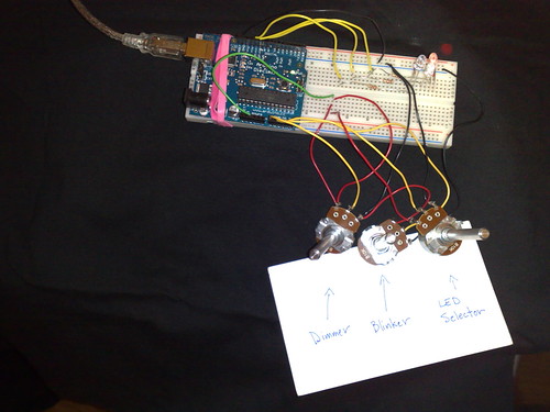
For this lab we learned how to use potentiometers as variable resistors. After soldering wires to our potentiometers we hooked them up to our Arduino boards. We loaded code onto the Arduino that allowed us to use one potentiometer to adjust an LED's brightness and another potentiometer to adjust the LED's blink rate.
For the first assignment I made each potentiometer control the brightness of a corresponding LED. Twisting each potentiometer adjusted the resistance to the LED, thus making it brighter or darker.
For my extra point I wanted to figure out how to allow the user to first select an LED by twisting a potentiometer, and then use the other two potentiometers to adjust brightness and blinking for that LED. The user could then twist the first potentiometer to another LED and adjust brightness and blinking, then twist the first potentiometer again to adjust the final LED's brightness and blinking. The program would then loop, lighting the LEDs in sequence with the user-selected brightness and blinking for each respective LED.
To select an LED via the potentiometer I divided the potentiometer's total range (0-1024) into three sub-ranges. If the potentiometer value is less than 342, one LED is selected. Between 343 and 680, another LED is selected. Above 680 a third LED is selected.
Components Used
Arduino Code (Three Potentiometers for Three LEDs - Controlling Brightness)
/*
* "Coffee-cup" Color Mixer:
* Code for mixing and reporting PWM-mediated color
* Assumes Arduino 0004 or higher, as it uses Serial.begin()-style communication
*
* Control 3 LEDs with 3 potentiometers
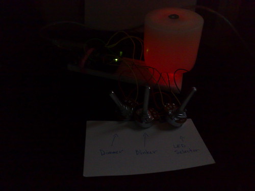
* If the LEDs are different colors, and are directed at diffusing surface (stuck in a
* a Ping-Pong ball, or placed in a paper coffee cup with a cut-out bottom and
* a white plastic lid), the colors will mix together.
*
* When you mix a color you like, stop adjusting the pots.
* The mix values that create that color will be reported via serial out.
*
* Standard colors for light mixing are Red, Green, and Blue, though you can mix
* with any three colors; Red + Blue + White would let you mix shades of red,
* blue, and purple (though no yellow, orange, green, or blue-green.)
*
* Put 220 Ohm resistors in line with pots, to prevent circuit from
* grounding out when the pots are at zero
*/
// Analog pin settings
int aIn = 0; // Potentiometers connected to analog pins 0, 1, and 2
int bIn = 1; // (Connect power to 5V and ground to analog ground)
int cIn = 2;
// Digital pin settings
int aOut = 9; // LEDs connected to digital pins 9, 10 and 11
int bOut = 10; // (Connect cathodes to digital ground)
int cOut = 11;
// Values
int aVal = 0; // Variables to store the input from the potentiometers
int bVal = 0;
int cVal = 0;
// Variables for comparing values between loops
int i = 0; // Loop counter
int wait = (1000); // Delay between most recent pot adjustment and output
int checkSum = 0; // Aggregate pot values
int prevCheckSum = 0;
int sens = 3; // Sensitivity theshold, to prevent small changes in
// pot values from triggering false reporting
// FLAGS
int PRINT = 1; // Set to 1 to output values
int DEBUG = 1; // Set to 1 to turn on debugging output
void setup()
{
pinMode(aOut, OUTPUT); // sets the digital pins as output
pinMode(bOut, OUTPUT);
pinMode(cOut, OUTPUT);
Serial.begin(9600); // Open serial communication for reporting
}
void loop()
{
i += 1; // Count loop
aVal = analogRead(aIn) / 4; // read input pins, convert to 0-255 scale
bVal = analogRead(bIn) / 4;
cVal = analogRead(cIn) / 4;
analogWrite(aOut, aVal); // Send new values to LEDs
analogWrite(bOut, bVal);
analogWrite(cOut, cVal);
if (i % wait == 0) // If enough time has passed...
{
checkSum = aVal+bVal+cVal; // ...add up the 3 values.
if ( abs(checkSum - prevCheckSum) > sens ) // If old and new values differ
// above sensitivity threshold
{
if (PRINT) // ...and if the PRINT flag is set...
{
Serial.print("A: "); // ...then print the values.
Serial.print(aVal);
Serial.print("\t");
Serial.print("B: ");
Serial.print(bVal);
Serial.print("\t");
Serial.print("C: ");
Serial.println(cVal);
PRINT = 0;
}
}
else
{
PRINT = 1; // Re-set the flag
}
prevCheckSum = checkSum; // Update the values
if (DEBUG) // If we want debugging output as well...
{
Serial.print(checkSum);
Serial.print("<=>");
Serial.print(prevCheckSum);
Serial.print("\tPrint: ");
Serial.println(PRINT);
}
}
}
Arduino Code (Extra Point)
/*
 * One potentiometer dims, the second potentiometer changes the blinking rate, and the third potentiometer
 * selects which LED you're adjusting.
 *
 * This code is a modification of code found at http://www.arduino.cc/en/Tutorial/AnalogInput
 *
 * Modified September 15, 2008
 * Andy Brooks <andy@ischool.berkeley.edu>
 */

int pot1Pin = 0;   // select the input pin for potentiometer 1 [Dimmer]
int pot2Pin = 1;   // select the input pin for potentiometer 2 [Blinker]
int pot3Pin = 2;   // select the input pon for potentiometer 3 [LED Selector]
int pot1Val = 0;   // variable to store the value coming from pot 1
int pot2Val = 0;   // variable to store the value coming from pot 2
int pot3Val = 0;   // variable to store the value coming from pot 3

int pot1ValRed = 0; // set dimmer value to 0
int pot2ValRed = 0; // set blinker value to 0

int pot1ValGreen = 0; // set dimmer value to 0
int pot2ValGreen = 0; // set blinker value to 0

int pot1ValBlue = 0; // set dimmer value to 0
int pot2ValBlue = 0; // set blinker value to 0

int led1Pin = 9;   // select the pin for the LED 1
int led2Pin = 10;  // select the pin for the LED 2
int led3Pin = 11;  // select the pin for the LED 3

void setup() {
 pinMode(led1Pin, OUTPUT);  // declare the led1Pin as an OUTPUT
 pinMode(led2Pin, OUTPUT);  // declare the led2Pin as an OUTPUT
 pinMode(led3Pin, OUTPUT);  // declare the led3Pin as an OUTPUT
}

void loop() {  // loops, constantly accepting value from pot3 (LED selector)
 pot3Val = analogRead(pot3Pin);

 analogWrite(led1Pin, pot1ValBlue/4); // dim LED to value from pot1
 delay(pot2ValBlue);                  // stop the program for some time, meaning, LED is on for this time
 analogWrite(led1Pin, 0);         // dim LED to completely dark (zero)
 delay(pot2ValBlue);

 analogWrite(led2Pin, pot1ValGreen/4); // dim LED to value from pot1
 delay(pot2ValGreen);                  // stop the program for some time, meaning, LED is on for this time
 analogWrite(led2Pin, 0);         // dim LED to completely dark (zero)
 delay(pot2ValGreen);

 analogWrite(led3Pin, pot1ValRed/4); // dim LED to value from pot1
 delay(pot2ValRed);                  // stop the program for some time, meaning, LED is on for this time
 analogWrite(led3Pin, 0);         // dim LED to completely dark (zero)
 delay(pot2ValRed);

 if (pot3Val <= 342) { // if you twist pot3 all the way to the left you can adjust the blue LED
 pot1Val = analogRead(pot1Pin);   // read the value from pot 1, between 0 - 1024, for dimming
 pot2Val = analogRead(pot2Pin);   // read the value from pot 2, between 0 - 1024, for blinking
 analogWrite(led1Pin, pot1Val/4); // dim LED to value from pot1
 delay(pot2Val);                  // stop the program for some time, meaning, LED is on for this time
 analogWrite(led1Pin, 0);         // dim LED to completely dark (zero)
 delay(pot2Val);                  // stop the program for some time, meaning, LED is OFF for this time
 pot1ValBlue = pot1Val;           // set blue LED's dimmer value equal to the value we just set with pot1.
 pot2ValBlue = pot2Val;           // set blue LED's blink value equal to the value we just set with pot2.
 }

 if (pot3Val > 343 && pot3Val <= 680) { // if you twist pot3 to the middle you can adjust the green LED
 pot1Val = analogRead(pot1Pin);   // read the value from pot 1, between 0 - 1024, for dimming
 pot2Val = analogRead(pot2Pin);   // read the value from pot 2, between 0 - 1024, for blinking
 analogWrite(led2Pin, pot1Val/4); // dim LED to value from pot1
 delay(pot2Val);                  // stop the program for some time, meaning, LED is on for this time
 analogWrite(led2Pin, 0);         // dim LED to completely dark (zero)
 delay(pot2Val);                  // stop the program for some time, meaning, LED is OFF for this time
 pot1ValGreen = pot1Val;          // set green LED's dimmer value equal to the value we just set with pot1.
 pot2ValGreen = pot2Val;          // set green LED's blink value equal to the value we just set with pot2.
 }

 if (pot3Val > 680) {    // if you twist pot3 all the way to the right you can adjust the red LED
 pot1Val = analogRead(pot1Pin);   // read the value from pot 1, between 0 - 1024, for dimming
 pot2Val = analogRead(pot2Pin);   // read the value from pot 2, between 0 - 1024, for blinking
 analogWrite(led3Pin, pot1Val/4); // dim LED to value from pot1
 delay(pot2Val);                  // stop the program for some time, meaning, LED is on for this time
 analogWrite(led3Pin, 0);         // dim LED to completely dark (zero)
 delay(pot2Val);                  // stop the program for some time, meaning, LED is OFF for this time

 pot1ValRed = pot1Val;             // set red LED's dimmer value equal to the value we just set with pot1.
 pot2ValRed = pot2Val;             // set red LED's blink value equal to the value we just set with pot2.
 }
}
Photographs