Assignment: Sensing: Potentiometers
Collaborators:
Collaborators: nick
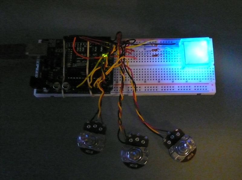
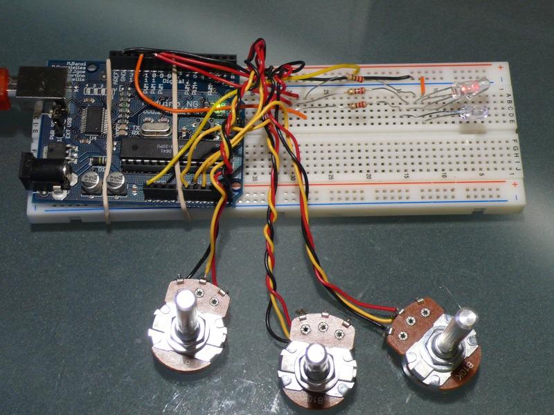
This lab was intended to explore the use of analog input devices with the arduino board.
We used 3 potentiometers to independently control Hue, Saturation, and Value on an array of RGB LEDs as described here.
/*
 * AnalogInput
 * Set hue with one pot, dim with one pot, flash with one pot
 *
 */

// pots
int dimPin = 1;
int huePin = 2;
int flashPin = 0;

// leds
int rPin = 11;
int gPin = 9;
int bPin = 10;

// values
int hueVal = 0;
int dimVal = 0;
int flashVal = 0;
int rVal = 0;
int gVal = 0;
int bVal = 0;
unsigned long x = 0;

void setup() {
  pinMode(rPin, OUTPUT);
  pinMode(gPin, OUTPUT);
  pinMode(bPin, OUTPUT);
  Serial.begin(9600);
}

void loop() {
  hueVal = analogRead(huePin);
  dimVal = analogRead(dimPin);
  flashVal = analogRead(flashPin);

  // determine hue
  x = (hueVal*255)/341;
  Serial.print(x);
  Serial.print(" : ");
  Serial.println(hueVal);
/*
  if (hueVal < 341) {
    rVal = 255-x;
    gVal = x;
    bVal = 0;
  }
  else if (hueVal < 683 && hueVal >= 341) {
    rVal = 0;
    gVal = 255-x;
    bVal = x;
  }
  else if (hueVal >= 683) {
    rVal = x;
    gVal = 0;
    bVal = 255-x;
  }
*/
  analogWrite(rPin, rVal);
  analogWrite(gPin, gVal);
  analogWrite(bPin, bVal);
  /*
  digitalWrite(rPin, HIGH);  // turn the ledPin on
   delay(val);                  // stop the program for some time
   digitalWrite(ledPin, LOW);   // turn the ledPin off
   delay(val);                  // stop the program for some time */
}