Assignment: Sensing: Potentiometers
Collaborators:
The purpose of this lab was to:
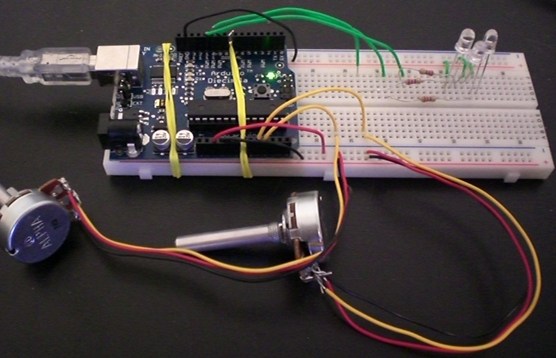
/*
 * one pot dims, the other pot changes the blinking rate
 * modification of the following
 * http://www.arduino.cc/en/Tutorial/AnalogInput
 */
int pot1Pin = 1;   // select the input pin for the potentiometer 1
int pot2Pin = 2;   // select the input pin for the potentiometer 2
int pot1Val = 0;   // variable to store the value coming from pot 1
int pot2Val = 0;   // variable to store the value coming from pot 2

int led9Pin = 9;    // select the pin for the LED 9
int led10Pin = 10;  // select the pin for the LED 10
int led11Pin = 11;  // select the pin for the LED 11

void setup() {
   pinMode(led9Pin, OUTPUT);  // declare the led9Pin as an OUTPUT
   pinMode(led10Pin, OUTPUT);  // declare the led10Pin as an OUTPUT
   pinMode(led11Pin, OUTPUT);  // declare the led11Pin as an OUTPUT
}
void loop() {
   /*********************************/
   /* Pot 1 will control brightness */
   /*********************************/
   pot1Val = analogRead(pot1Pin);     // read the value from pot 1, between 0 - 1024, for dimming
   Serial.println(pot1Val);
   analogWrite(led9Pin, pot1Val/4);   // dim led9Pin to value from pot1
   analogWrite(led10Pin, pot1Val/4);  // dim led10Pin to value from pot1
   analogWrite(led11Pin, pot1Val/4);  // dim led11Pin to value from pot1

   /*******************************/
   /* Pot 2 will control blinking */
   /*******************************/
   pot2Val = analogRead(pot2Pin);   // read the value from pot 2, between 0 - 1024, for blinking
   delay(pot2Val);                  // stop the program for some time, meaning, LED is on for this time
   analogWrite(led9Pin, 0);         // dim LED to completely dark (zero)
   analogWrite(led10Pin, 0);         // dim LED to completely dark (zero)
   analogWrite(led11Pin, 0);         // dim LED to completely dark (zero)
   delay(pot2Val);                  // stop the program for some time, meaning, LED is OFF for this time
}
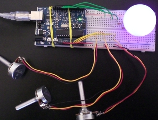
I found that using analog inputs rather than keyboard inputs for color mixing was much more intuitive. I was able to achieve better color blends within my ping pong ball because it was easier to make precise color adjustments using the knobs.
/*
* Analog color mixer.  Code based on code that I found from
* the Arduino website at:
* http://www.arduino.cc/en/Tutorial/LEDColorMixerWith3Potentiometers
*/

// Analog pin settings
int aInRed   = 0;    // Potentiometers connected to analog pins 0, 1, and 2
int bInGreen = 1;    //   (Connect power to 5V and ground to analog ground)
int cInBlue  = 2;

// Digital pin settings
int aOutRed   = 9;   // LEDs connected to digital pins 9, 10 and 11
int bOutGreen = 10;  //   (Connect cathodes to digital ground)
int cOutBlue  = 11;

// Values
int aValRed   = 0;   // Variables to store the input from the potentiometers
int bValGreen = 0;
int cValBlue  = 0;

// Variables for comparing values between loops
int i = 0;            // Loop counter
int wait = (1000);    // Delay between most recent pot adjustment and output

int checkSum     = 0; // Aggregate pot values
int prevCheckSum = 0;
int sens         = 3; // Sensitivity theshold, to prevent small changes in
                      // pot values from triggering false reporting
// FLAGS
int PRINT = 1; // Set to 1 to output values
int DEBUG = 1; // Set to 1 to turn on debugging output

void setup()
{
  pinMode(aOutRed, OUTPUT);   // sets the digital pins as output
  pinMode(bOutGreen, OUTPUT);
  pinMode(cOutBlue, OUTPUT);
  Serial.begin(9600);     // Open serial communication for reporting
}

void loop()
{
  i += 1; // Count loop

  aValRed = analogRead(aInRed) / 4;  // read input pins, convert to 0-255 scale
  bValGreen = analogRead(bInGreen) / 4;
  cValBlue = analogRead(cInBlue) / 4;

  analogWrite(aOutRed, aValRed);    // Send new values to LEDs
  analogWrite(bOutGreen, bValGreen);
  analogWrite(cOutBlue, cValBlue);

  if (i % wait == 0)                // If enough time has passed...
  {
    checkSum = aValRed+bValGreen+cValBlue;      // ...add up the 3 values.
    if ( abs(checkSum - prevCheckSum) > sens )   // If old and new values differ
                                                  // above sensitivity threshold
    {
      if (PRINT)                    // ...and if the PRINT flag is set...
      {
        Serial.print("A (Red): ");        // ...then print the values.
        Serial.print(aValRed);
        Serial.print("\t");
        Serial.print("B (Green): ");
        Serial.print(bValGreen);
        Serial.print("\t");
        Serial.print("C: (Blue): ");
        Serial.println(cValBlue);
        PRINT = 0;
      }
    }
    else
    {
      PRINT = 1;  // Re-set the flag
    }
    prevCheckSum = checkSum;  // Update the values

    if (DEBUG)   // If we want debugging output as well...
    {
      Serial.print(checkSum);
      Serial.print("<=>");
      Serial.print(prevCheckSum);
      Serial.print("\tPrint: ");
      Serial.println(PRINT);
    }
  }
}
This code cycles between red, green, and blue based on input from the pot mapped to pin 0.
/*
 * Experiment 3:  RGB Blinker
 * This circuit makes the LED lights blink from Red to Blue to Green.
 * The rate with which the colors cycle depends on the pot input from
 * the 0-pin.  I adapted this code from the "1b_SinglePotControlsBlinking" script:
 */
int ledPin = 9;     // the "active" pin
int potPin = 0;     // select the input pin for the potentiometer
int redPin   = 9;   // red LED pin
int greenPin = 10;  // green LED pin
int bluePin  = 11;  // blue LED pin
int val = 0;        // variable to store the value coming from the sensor

int newColor = 0;
int counter = 0;
void setup() {
  pinMode(ledPin, OUTPUT);  // declare the ledPin as an OUTPUT
}
void loop() {
  ++counter;
  newColor = counter % 3; //take the current color plus the counter modulus 3.
  Serial.println("New color: " + newColor);
  switch(newColor)
  {
     case 0:
       analogWrite(redPin, 255);    // Send new values to LEDs
       analogWrite(greenPin, 0);
       analogWrite(bluePin, 0);
       ledPin = redPin;
       break;
     case 1:
       ledPin = greenPin;
       analogWrite(redPin, 0);    // Send new values to LEDs
       analogWrite(greenPin, 255);
       analogWrite(bluePin, 0);
       break;
     case 2:
       ledPin = bluePin;
       analogWrite(redPin, 0);    // Send new values to LEDs
       analogWrite(greenPin, 0);
       analogWrite(bluePin, 255);
       break;
  }
  val = analogRead(potPin);    // read the value from the sensor
  digitalWrite(ledPin, HIGH);  // turn the ledPin on
  delay(val);                  // stop the program for some time
  //digitalWrite(ledPin, LOW);   // turn the ledPin off
  //delay(val);                  // stop the program for some time
}