Lecture Slides
Available here.
Readings in Physical Computing
-
Analog input: p. 102-104
-
Soldering: p. 41-42
Before the Lab
You should have already successfully built the 3 LED (RGB) circuit and gotten them to fade with various color combinations. Congratulations!
In Lab Exercise
Objective
In this lab, we explore analog input. Specifically, we’ll be looking at variable resistance devices known as potentiometers or “pots” for short. In exploring analog input, we will use Arduino to read pot values and control the LEDs as a function of the pot. We’ll also be moving away from the more elementary circuit diagrams to the more advanced circuit schematic diagrams.
Activities
Part 1: Soldering
1) Take 1 red, 1 black, 1 yellow wires, and 1 pot (One pot is in your kit).
2) Strip off about ¼” of the insulation from each of these wires.
3) Solder wires to the pot.
a) Soldering often requires more than 2 hands. That’s why we have “helping hands”. Use them like in the image below to secure your pot and your wire.
b) To solder, you place the soldering iron on the wire/terminal and heat the joint, then apply the solder (keep the tip on the joint), remove the solder, then remove the iron in that order.
c) Let it cool before moving it around (it’ll take just a few seconds)

Part 2: Controlling one LED from the one Pot
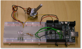
1) Extend your 3 LED circuit so that it includes a pot. Follow the circuit diagrammed below
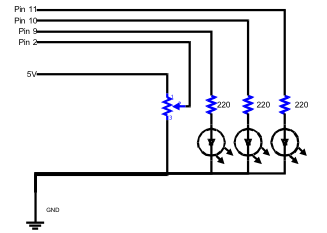
2) On the course website, there are two programs which allow you to use the pot to control the brightness of an LED or the blinking speed of the LED. Make sure the pins in the code match the pins you used for the LEDs and the pot.
Part 3: Multiple Pots controlling multiple LEDs
1) There are two options for this part.
a) Use one pot to control the brightness and the other pot to control the blinking.
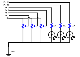
b) Use three pots, each pot controls the brightness of RGB Hue/Colors. (You will need to get extra pots from us and solder on the wires).
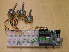
2) Extend your circuit to include two or three pots. The circuit diagram and image for three pots are given below. The two pot setup is really similar.
3) On the website is code that allows you to use 3 pots (2a) or 2 pots (2b). Make sure the pins in the code match the pins you used for the LEDs and the pot.
Homework: Due February 19 at 11:59PM
Use multiple pots to control your LEDs
Option 1: One pot controls brightness, another pot controls blinking
Option 2: 3 Pots for 3 LEDs (each pot controls brightness of RGB Hue / colors
Extra points:
Come up with an interesting mapping between the rotational position pot and LED output.
Click
here to post your assignment
